Activity
1. Let’s program a counter with Arduino! To do this, open your Tinkercad account to start the activity.
• If you already have an account, click Log in
• If you do not have an account, click on SIGN UP NOW and ask an adult for help with the following steps.
For security reasons, and to protect your privacy, we recommend the following:
– avoid using your full name as your username;
– use a password with a wide range of characters (uppercase, numbers and symbols), and never personal data such as your date of birth.
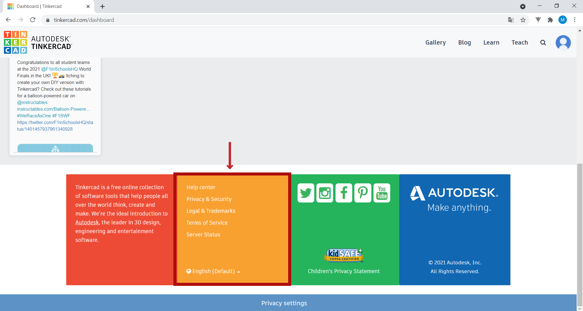
If Tinkercad is not in your language, you can change the language at the bottom of the home page.
NOTE: You can click on the tool’s demo images to enlarge them.

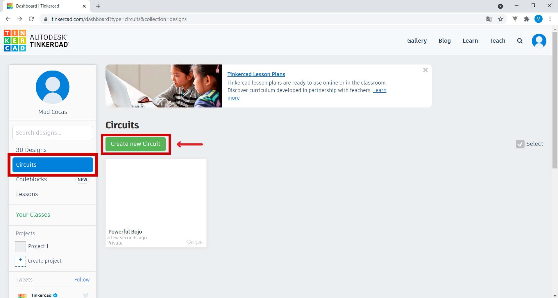
2. Once you have created your account, on the right-hand side of the home page, click on Circuits. Then click on the green Create new Circuit button.
When you click on this button, the Tinkercad interface will look like this:
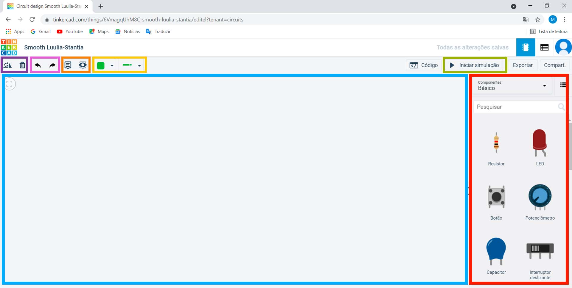
• On the right side of the screen, in the area marked in red, you will find a list of components you can use;
• In the area marked in green, you will find the “Start simulation” button. Click on this button whenever you want to test how your circuit works;
• In the area marked in purple, you will find two buttons: one button to rotate the component and another to delete it;
• In the area marked in pink, you can undo or redo the actions you have done in the project;
• In the area marked in orange, you can create annotations and display or hide them;
• In the area marked in yellow, you can choose the colour and type of connection wires to be used;
• To use a component, simply select it and drag it to the working area, marked in blue.
3. On the right side of the screen, in the area previously marked in red, search for the word “Arduino”. Drag the Arduino Uno R3 to the working area.
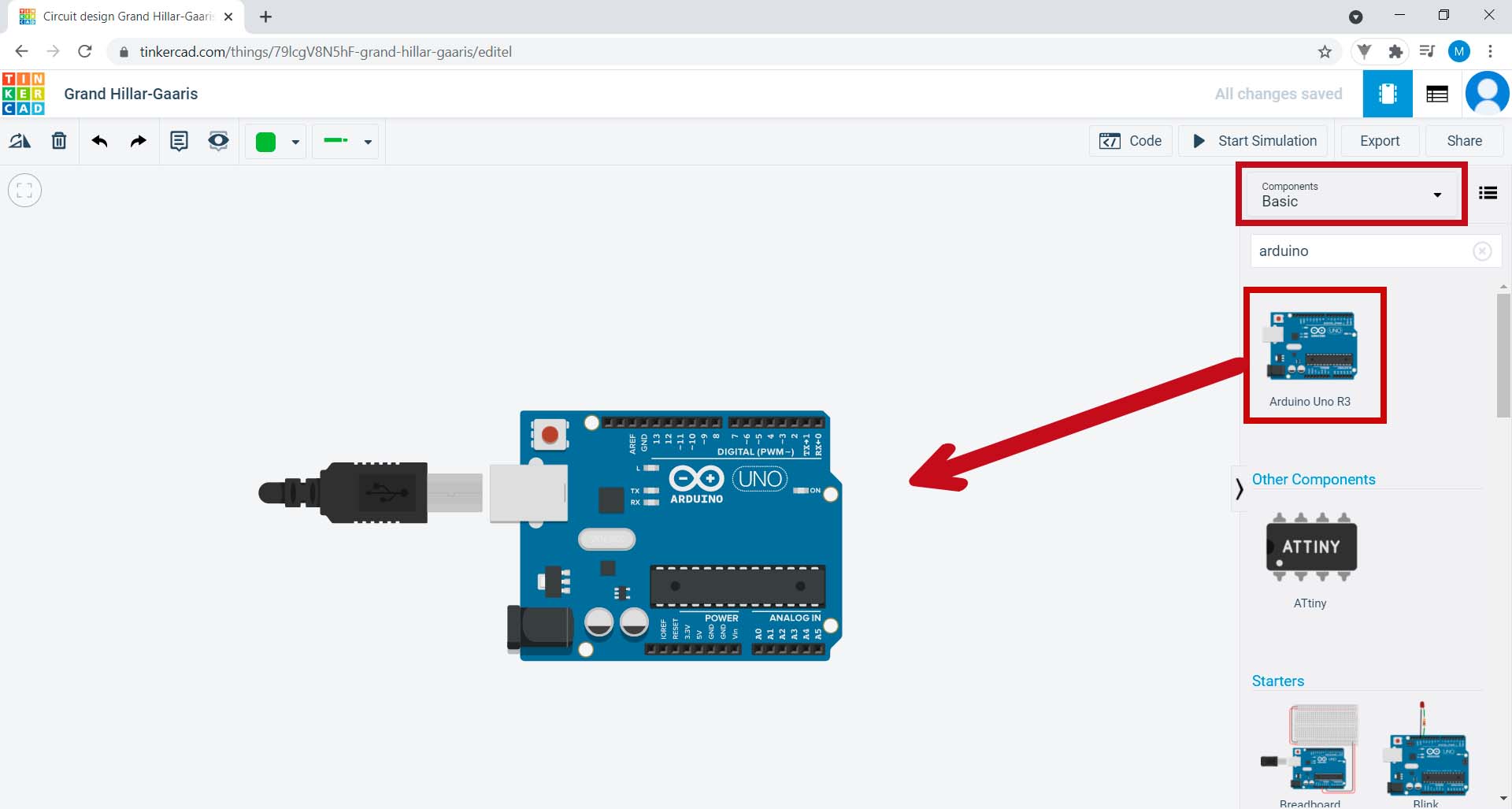
Arduino is a prototyping platform, meaning that it allows us to create projects involving electronics and programming. For the programming part, we already have everything we need. Let’s now build an electric circuit.
4. First, on the right-hand side of the screen, search for “board”. Drag the Breadboard Small onto the working area, as shown in the image.
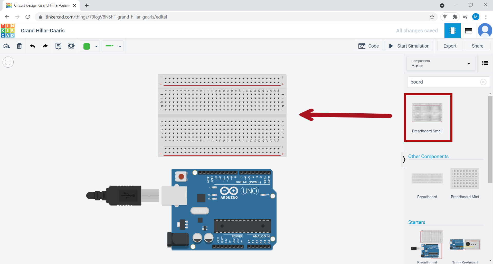
What you have dragged is also known as a breadboard. This is the board where you will build the circuit. The breadboard contains several small holes interconnected by columns. These allow us to simplify circuits by avoiding the use of too many wires. To create a wire, click on the hole where you want to put it, and then click again on the spot where you are supposed to connect that wire, which may or may not be the breadboard.
In the menu bar, you can change the wire’s colour by clicking on the green button. You can also delete the wire. To do this, select it by clicking on it and, in the menu bar, click on the Trash button (button in the shape of a trash bucket) or use the Delete key on the keyboard.

5. Let’s assemble the following circuit:
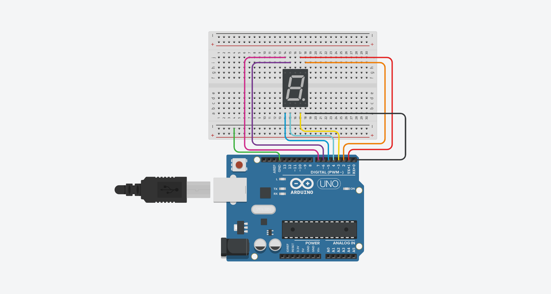
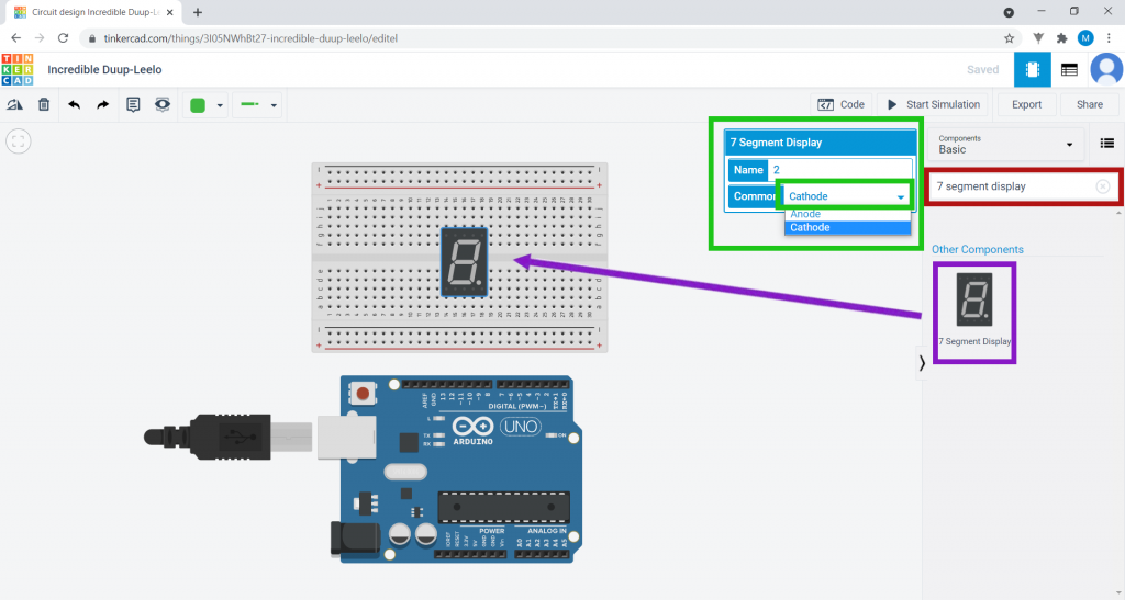
You will need a seven segment display and a resistor. The seven segment display is a small screen showing numbers made up of segments/bright lines, as seen on some watches and alarm clocks.
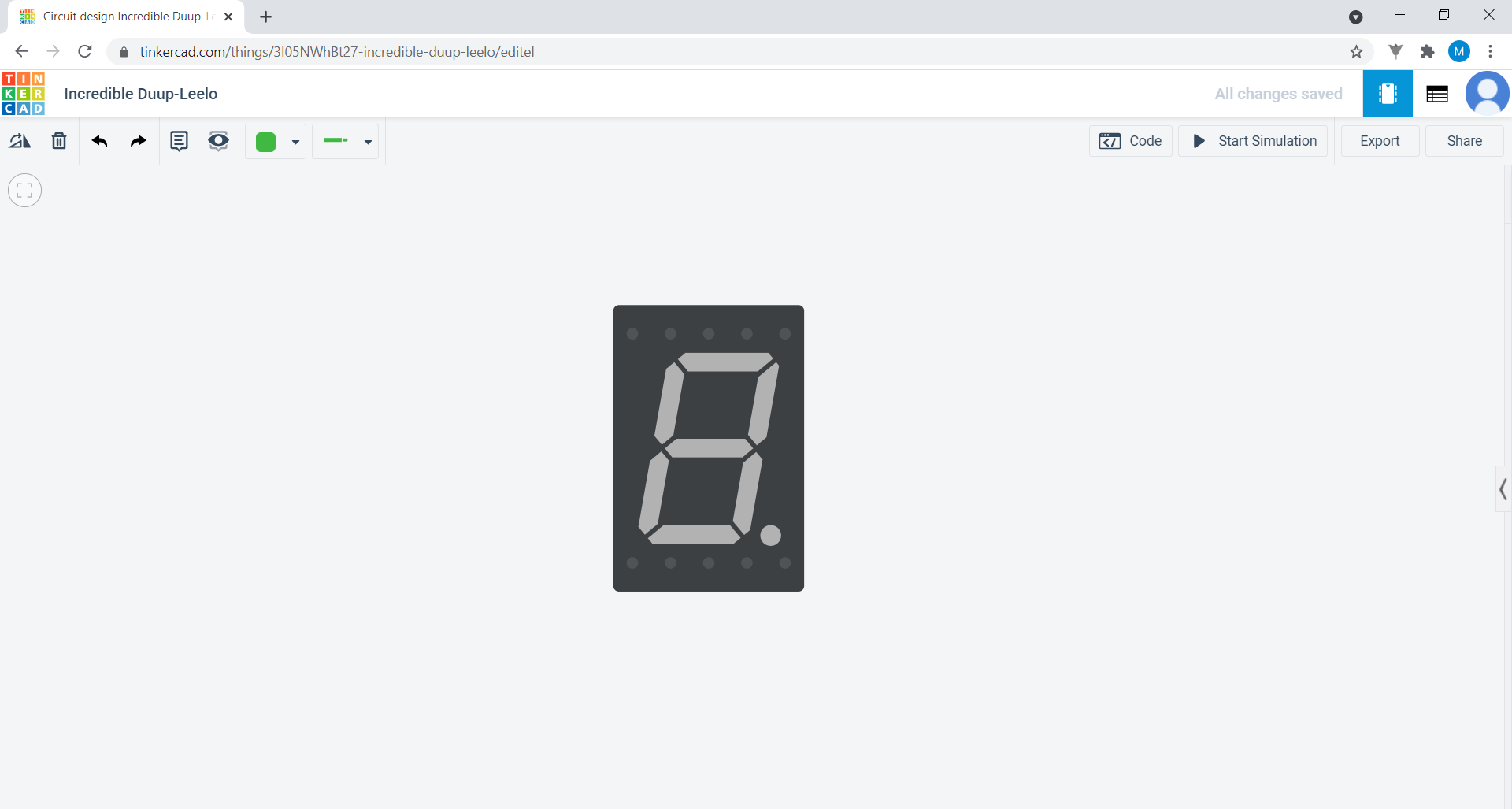
Search for “7 segment display” in the search bar.
Drag the component on top of the breadboard. As you can see, a box has appeared on the right side of this component, where the display’s settings appear. Under Common, select the Cathode option.
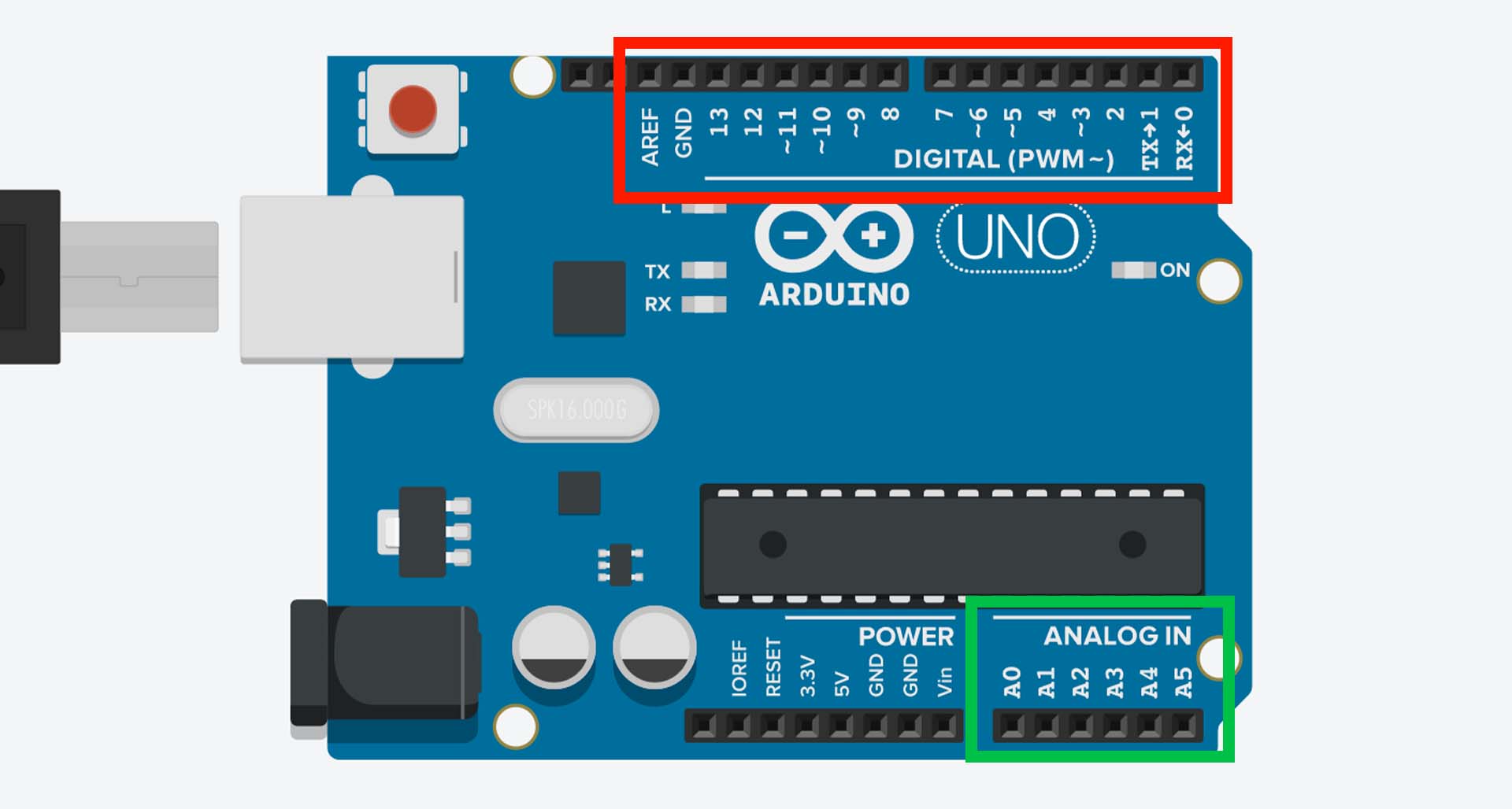
Next, you’ll connect the wires from the breadboard to the Arduino’s pins. The Arduino pins allow signals to flow from the circuit to the Arduino and then to the computer, and vice versa. These signals can be digital when they accept two statuses, and analogue when they accept continuous signals. Digital signals are associated with actions such as turning a light on or off, while analogue signals are associated with measurements of temperature, humidity, etc.
These signals are received and transmitted by the Arduino through two major types of pins:
• The digital ones marked in red;
• The analogue ones marked in green.
Within the digital pins, there are pins marked with “~”. These digital pins are special, because they simulate analogue signals through digital signals. These are called PWM (Pulse-width modulation).
Below are some other pins you should know about:
• RES – RESET allows you to reset the Arduino externally by programming the physical board;
• 3.3 V – Supplies the Arduino with 3.3 V and a maximum current of 50 mA;
• 5 V – Supplies the Arduino with 5 V and a maximum current of 50 mA; GND – The GROUND.

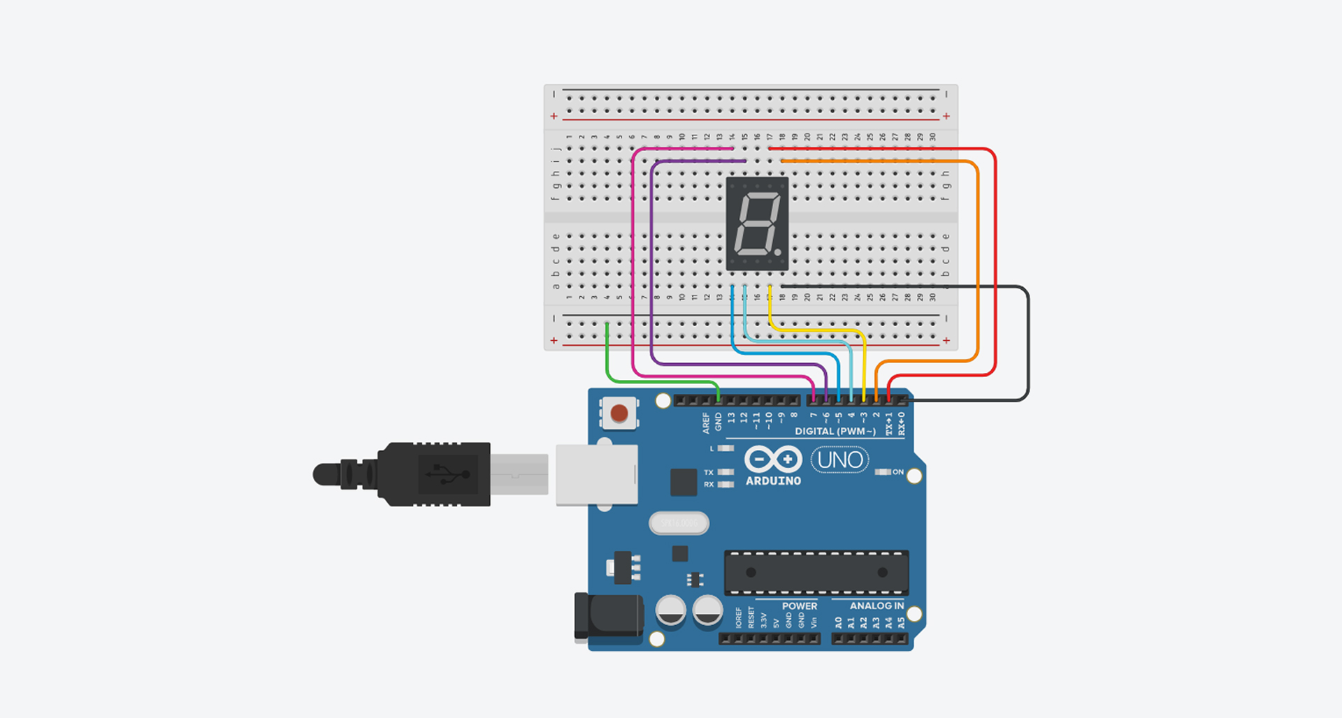
Connect the various wires from the breadboard to the Arduino’s pins.
• the green wire connects the second to last horizontal line of the breadboard to the GND pin of the Arduino;
• the black wire connects the last pin, counting from left to right, which is below the seven segment display, to pin 0 of the Arduino;
• the red wire connects the second to last pin, counting from left to right, which is above the display to pin 1 of the Arduino;
• the orange wire connects the last pin, counting from left to right, which is above the display, to pin 2 of the Arduino;
• the yellow wire connects the second to last pin, counting from left to right, below the display to pin 3 of the Arduino;
• the turquoise blue wire connects the second pin, counting from left to right, which is below the display, to pin 4 of the Arduino;
• the blue wire connects the first pin, counting from left to right, below the display, to pin 5 of the Arduino;
• the purple wire connects the second pin, counting from left to right, which is above the display, to pin 6 of the Arduino;
• the pink wire connects the first pin, counting from left to right, which is above the display, to pin 7 of the Arduino.
The circuit receives electricity from the Arduino. However, it is too much for the use you are going give it. To remove this “excess” electricity, search for “resistor” in the search bar, and connect the resistor to the second to last horizontal line of the breadboard, as shown in the image:
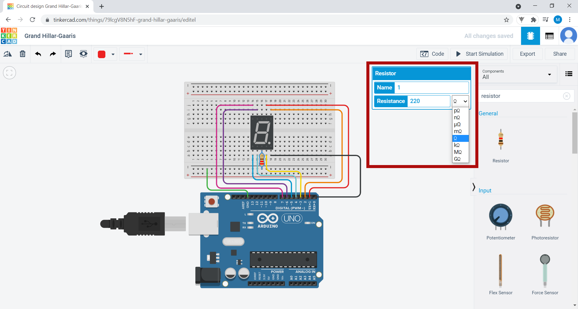
The unit of measurement of electrical resistance is the Ohm (Ω). When you put the resistor on the board, a box will appear that allows you to change the value of your resistor. For this circuit, change the resistance settings to 220Ω by typing “220” in front of the Resistance field and selecting the unit Ω.
6. Now that you have assembled the circuit, you will give it instructions: tell it, through code, what it has to do to work. First, in the menu bar on the right-hand side of the screen, click on the Code button. A window will appear below. Then click on the arrow next to the word Blocks and select the Text option. A new window will appear. Click on Continue.
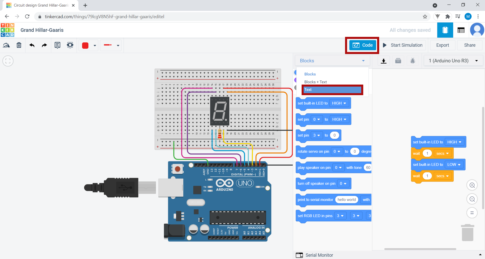
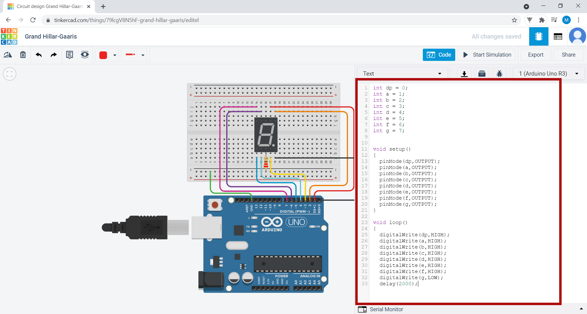
Some previously written code exists as an example. Delete it and write in the following code:
7. Hover the mouse cursor over the display. If you look, all the pins on the display are identified, with each one corresponding to one of the bright lines on the display. We connect a digital pin of the Arduino, also properly identified, to each pin of the display.

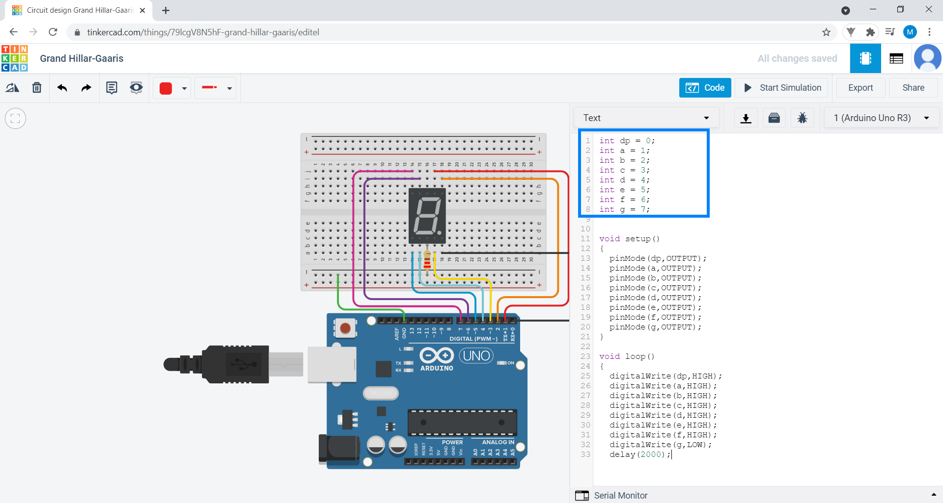
8. In the area highlighted in blue in the image, using the code, we give a name to each of the display pins, taking their identification into account, and determine which Arduino pins they are connected to. For example, the DP pin of the display is called “dp” in the code, and is connected to pin 0, so the code corresponding to that pin is int dp = 0.
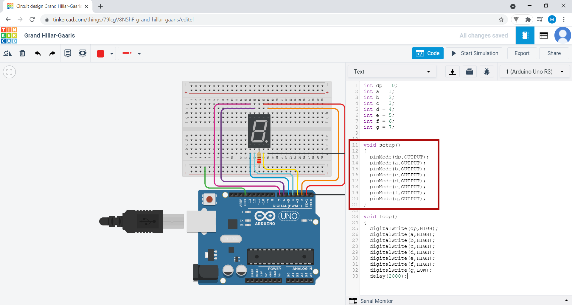
In the area highlighted in red, we use the pinMode() function. This tells the computer whether a particular component gives or receives information. In this case, it tells us whether the seven segment display gives (INPUT) or receives (OUTPUT) information to/from the Arduino.
Since the Arduino is “telling” the display to do something, this means that the display is receiving information, so it is identified with the OUTPUT code. We create one line of code for each pin of the display.
The previous lines of code are written “inside” the void setup(). Everything written inside the void setup() function is read by the Arduino only once.
In the purple highlighted area, we tell each of the segments (or lines) of the seven segment display what they have to do. For instance:
• When you type digitalWrite(a, HIGH);, you are telling the line corresponding to pin A of the display (referred to as “a” in the code) to light up (HIGH);
• when you type delay(2000), you are telling the lines to wait 2 seconds; delay() counts the time in milliseconds (ms), so 2000 ms = 2s;
• when you type digitalWrite(a, LOW);, you are telling the line corresponding to pin A of the display (referred to as “a” in the code) to turn off (LOW); The code is written “inside” the void loop()function. Everything written inside void loop() is read by the Arduino an infinite number of times (until you tell it to stop).

Now that you know which actions your existing lines of code correspond to, copy the rest of the code!
  digitalWrite(dp,HIGH);
  digitalWrite(a,LOW);
  digitalWrite(b,HIGH);
  digitalWrite(c,HIGH);
  digitalWrite(d,LOW);
  digitalWrite(e,LOW);
  digitalWrite(f,LOW);
  digitalWrite(g,LOW);
  delay(2000);
  digitalWrite(dp,HIGH);
  digitalWrite(a,HIGH);
  digitalWrite(b,HIGH);
  digitalWrite(c,LOW);
  digitalWrite(d,HIGH);
  digitalWrite(e,HIGH);
  digitalWrite(f,LOW);
  digitalWrite(g,HIGH);
  delay(2000);
  digitalWrite(dp,HIGH);
  digitalWrite(a,HIGH);
  digitalWrite(b,HIGH);
  digitalWrite(c,HIGH);
  digitalWrite(d,HIGH);
  digitalWrite(e,LOW);
  digitalWrite(f,LOW);
  digitalWrite(g,HIGH);
  delay(2000);
  digitalWrite(dp,HIGH);
  digitalWrite(a,LOW);
  digitalWrite(b,HIGH);
  digitalWrite(c,HIGH);
  digitalWrite(d,LOW);
  digitalWrite(e,LOW);
  digitalWrite(f,HIGH);
  digitalWrite(g,HIGH);
  delay(2000);
  digitalWrite(dp,HIGH);
  digitalWrite(a,HIGH);
  digitalWrite(b,LOW);
  digitalWrite(c,HIGH);
  digitalWrite(d,HIGH);
  digitalWrite(e,LOW);
  digitalWrite(f,HIGH);
  digitalWrite(g,HIGH);
  delay(2000);
  digitalWrite(dp,HIGH);
  digitalWrite(a,HIGH);
  digitalWrite(b,LOW);
  digitalWrite(c,HIGH);
  digitalWrite(d,HIGH);
  digitalWrite(e,HIGH);
  digitalWrite(f,HIGH);
  digitalWrite(g,HIGH);
  delay(2000);
}
9. Click on the Start simulation button to see what happens. Watch: the display counts down from 0 to 6!
10. Explore Tinkercad and create new circuits with Arduino.