Activity
1. From cellphones to planes, electronics is what makes our world work. In electronics, there are small parts called components and, when you put them together, you turn lights on and off or even get toys to move!

2. But you need energy for this to work. You can get energy from batteries, for example. This energy is conducted to the components through colored wires and the breadboard, a board where circuits are built. This is made up of little holes connected to each other via columns.
SIDE NOTE: You may click the images to amplify.

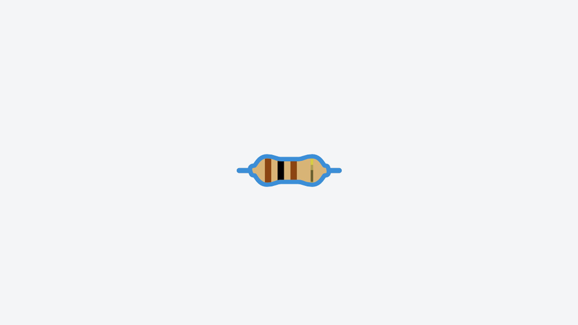
But be careful: sometimes you have more energy than you need. Resistors are used to get rid of this excess energy. The unit of measurement for electrical resistance is the ohm (Ω).
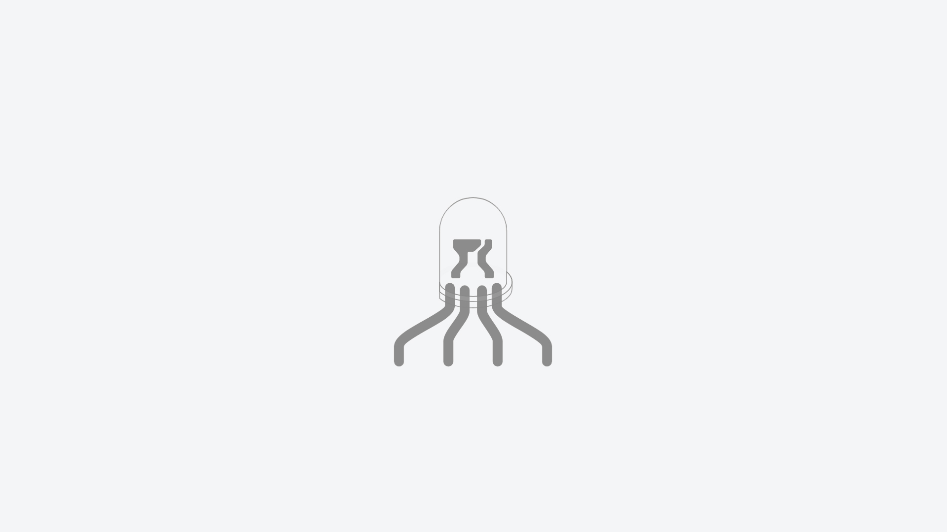
3. In this activity, you’ll learn to connect a LED, a component that gives light! The LED you’ll be using is special. It’s an RGB LED.
RGB means Red, Green and Blue. Red, green and blue are the three primary colors of light. You can make all the other colors using just these three and if you put all three together… you get white!
The RGB LED has the three colors: red, green and blue. You’ll find out which one corresponds to which leg.
4. Open your Tinkercad account to start the activity.
• If you already have an account created, click Sign in.
• If you don’t have an account, click on the JOIN NOW button and ask an adult for help in performing the following steps.
For security reasons and in order to protect our privacy, it is recommended that you:
– avoid using your full name as a username;
– choose a password that contains as many elements as possible (upper-case and lower-case letters, numbers and special characters), but does not include personal data, such as your date of birth.
If Tinkercad isn’t in the language you want, you can change it in the orange block at the bottom of the homepage.

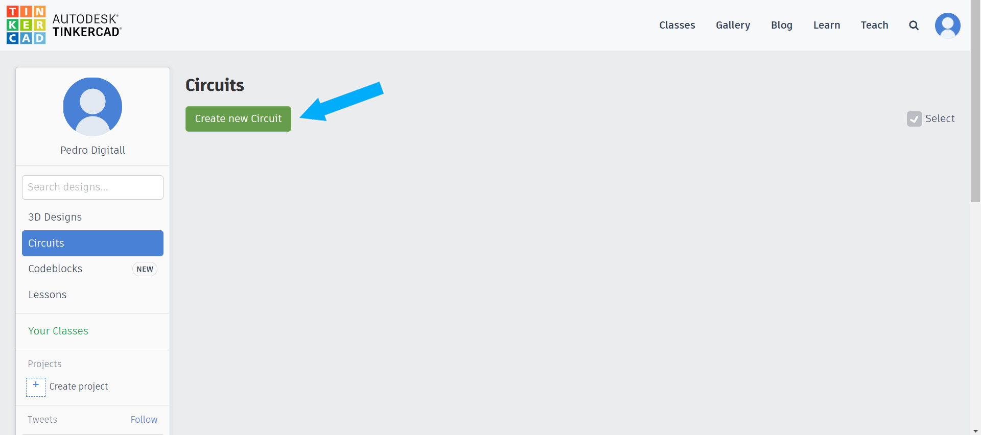
5. Go to Circuits and select Create new Circuit.
When you create a new circuit, you’ll see the Tinkercad interface like this:
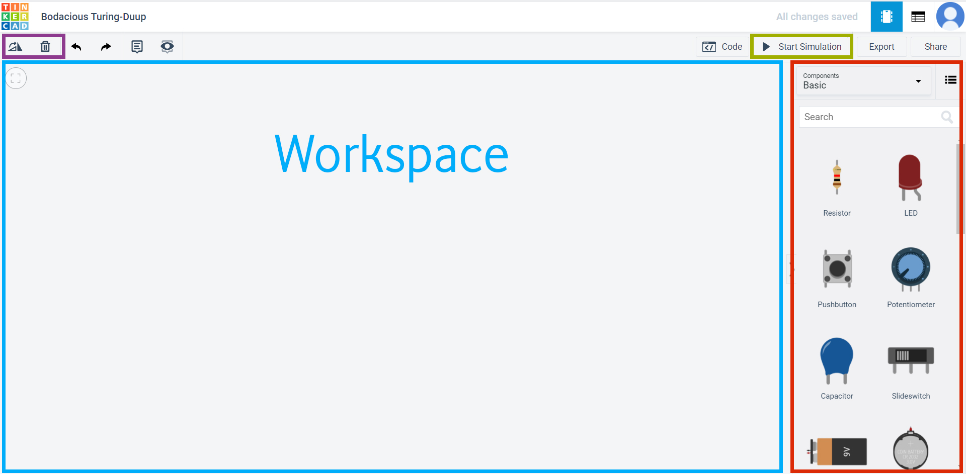
• There’s a list of the components you can use on the right of the screen, highlighted in red;
• The Start Simulation button is in the area highlighted in green. Press this button whenever you want to test how your circuit is working;
• There are two buttons in the area highlighted in purple, one to rotate the component and the other to delete it;
• If you want to use a component, just select it and drag it to the workplane (highlighted in blue).
6. Search for breadboard. Drag the breadboard mini to the Workspace.
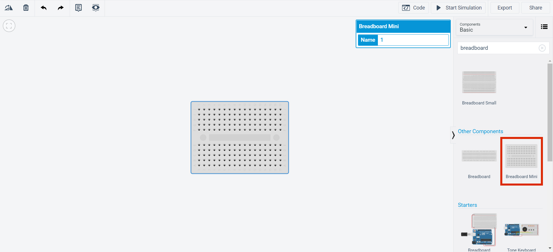
You’re going to build your circuit on the breadboard. It has lots of little holes connected to each other via columns. These allow you to simplify circuits by avoiding the use of lots of wires.
7. Let’s build this circuit:
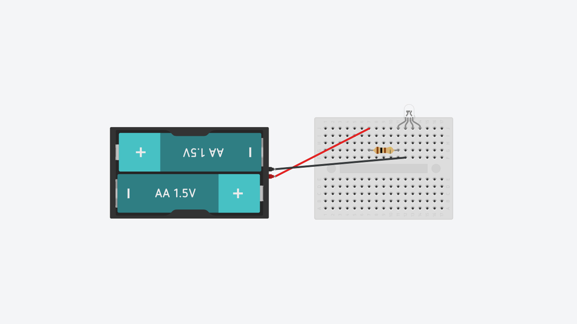
To do this, you’ll need:
• 1 resistor (search for resistor in the components);
• 1 RGB LED (search for RGB LED in the components);
• 1 x 1.5 V battery (search for 1.5 V battery in the components).
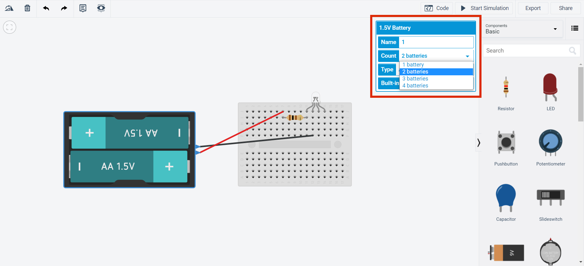
8. Click on the resistor and change the settings to 100 Ω. When you put a resistor on the board, a box will appear for you to change the resistance value. Write “100” as the Resistance value and select the unit Ω.
Next, select the 1,5 V battery and change its count to 2. When we say 1,5 V, we’re talking about electrical voltage. The unit of measurement for electrical voltage is the volt (V).
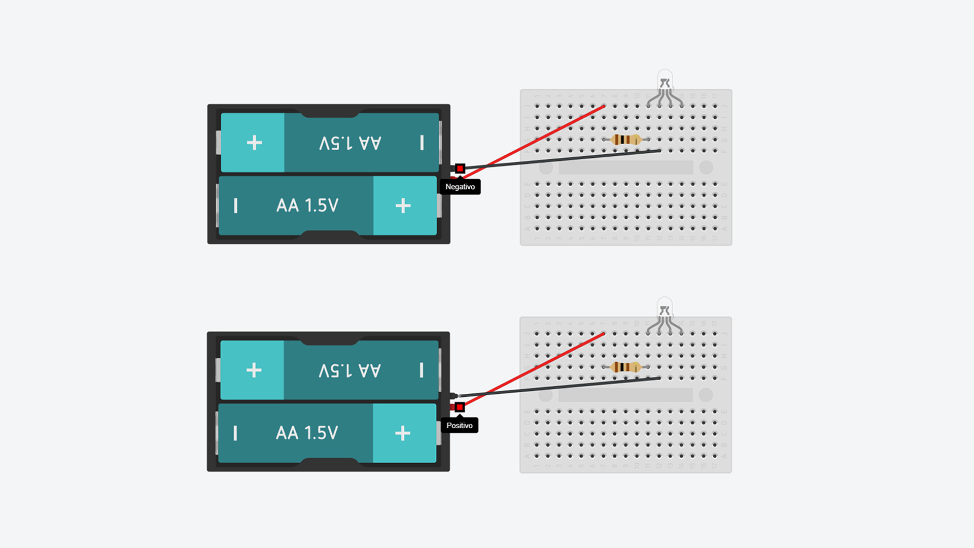
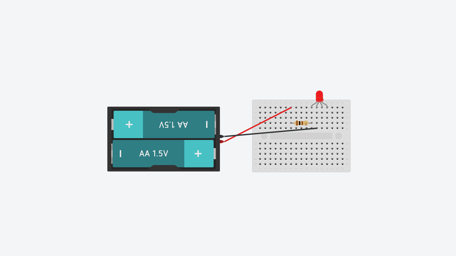
Finally, take a look at the two ends of the battery. If you hover over them with the mouse, you’ll seen that one says negative and the other says positive. Be careful when you’re building the circuit: the black wire must be connected to the negative terminal of the battery and the second leg of the LED.
9. Click on Start Simulation and see what happens. Notice that the first leg of the LED corresponds to red.
10. Click on Stop Simulation. Now connect the resistor to the third leg of the LED, as in the circuit below, and click on Start Simulation.
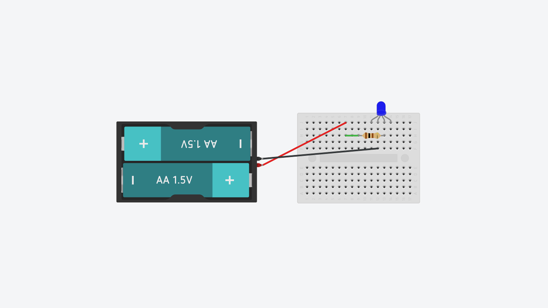
The third leg corresponds to blue! Let’s check that the last one corresponds to green.
11. Click on Stop Simulation. Finally, connect the resistor to the last leg of the LED, as in the circuit below, and click on Start Simulation.

This shows that the last leg corresponds to green!
12. And what happens if, using the resistors, you connect all the legs at the same time? Try it out!
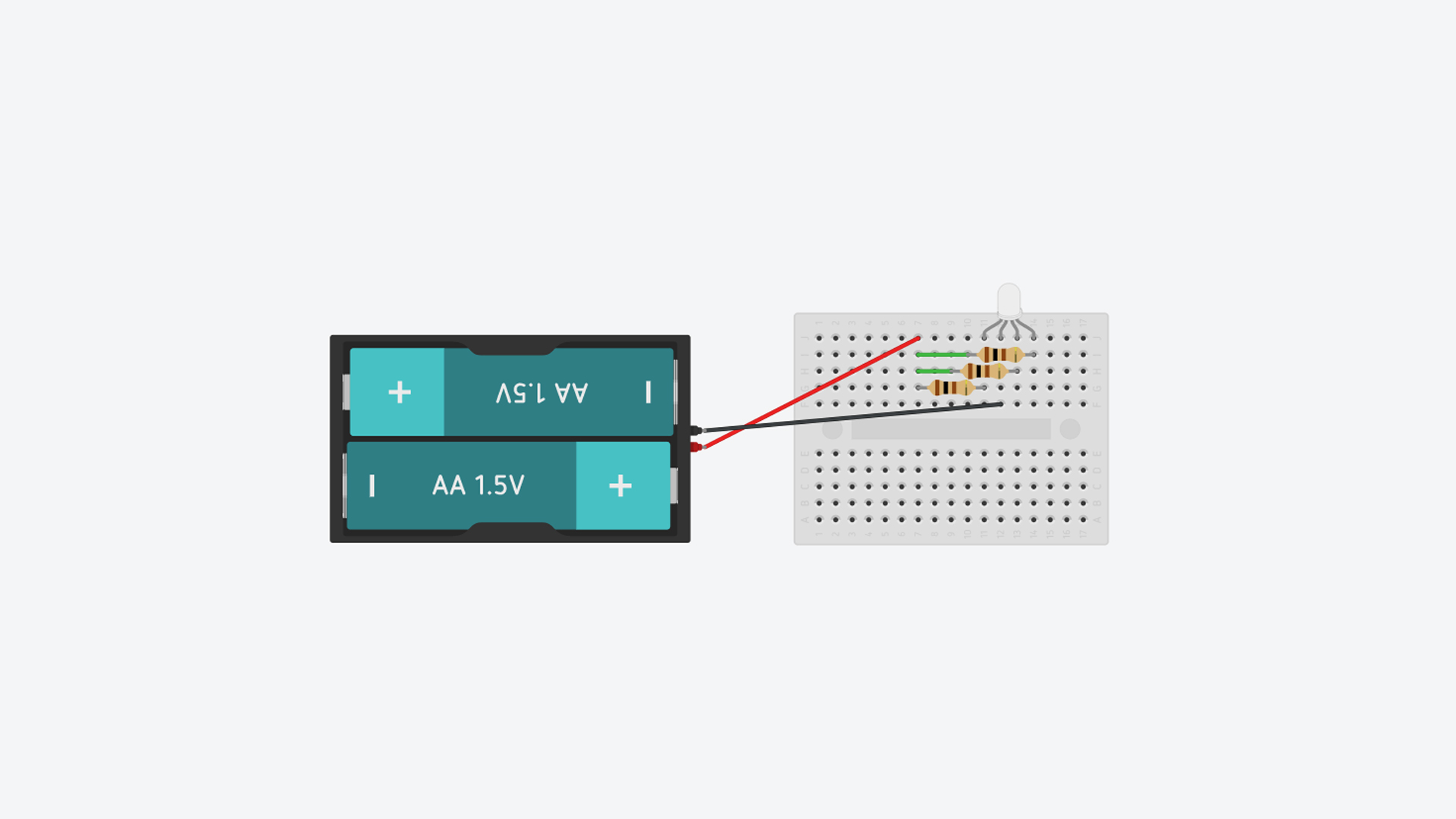
The LED produces white light! Congratulations! Now that you know how to work with the circuits in Tinkercad, keep exploring and create your own circuits.