Activity
1. Let’s program traffic lights! Have you got everything ready? Open yourTinkercad account to start the activity.
• If you already have an account created, click Sign in.
• If you don’t have an account, click on the JOIN NOW button and ask an adult for help in performing the following steps.
For security reasons and in order to protect our privacy, it is recommended that you:
– avoid using your full name as a username;
– choose a password that contains as many elements as possible (upper-case and lower-case letters, numbers and special characters), but does not include personal data, such as your date of birth.
If Tinkercad isn’t in the language you want, you can change it in the orange block at the bottom of the homepage.
SIDE NOTE: You may click the images to amplify.


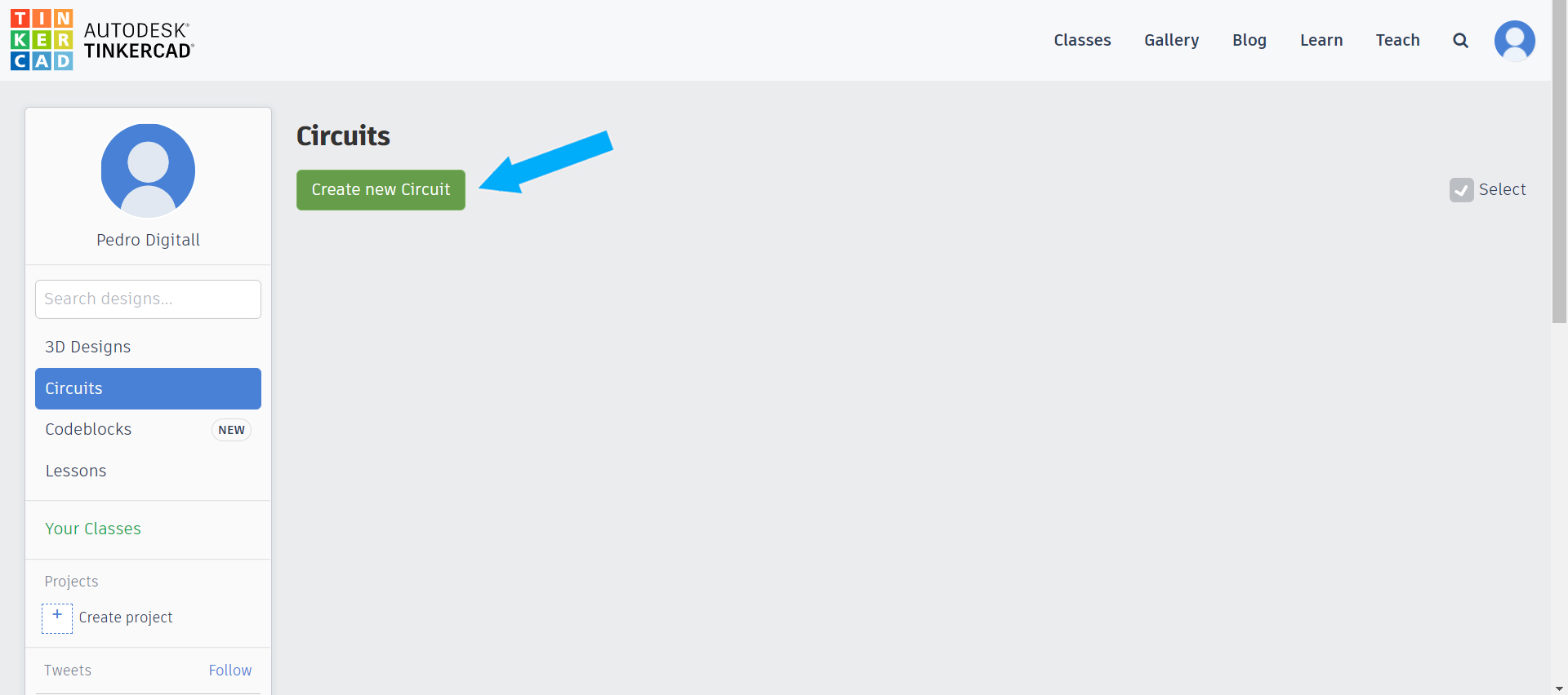
2. Go to Circuits and select Create new Circuit.
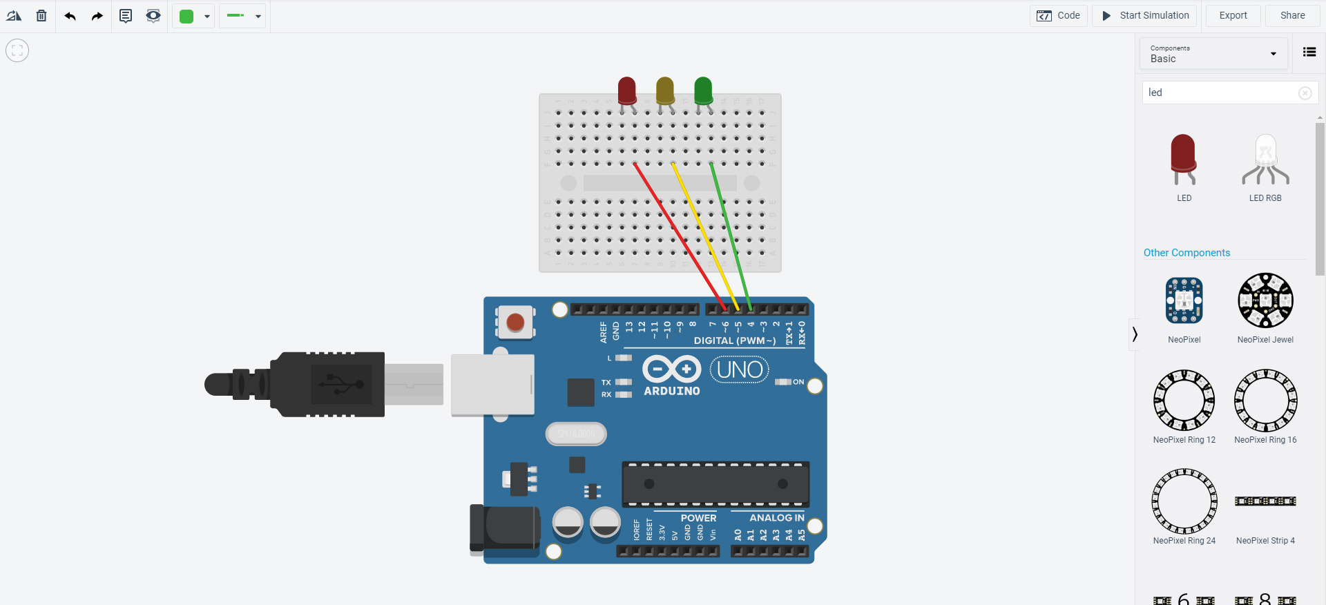
When you create a new circuit, you’ll see the Tinkercad interface like this:
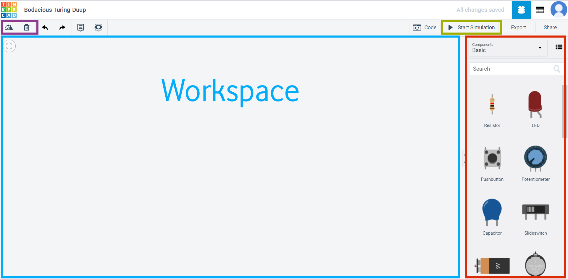
• There’s a list of components you can use on the right of the screen, highlighted in red;
• The Start Simulation button is in the area highlighted in green. Press this button whenever you want to test how your circuit is working;
• There are two buttons in the area highlighted in purple, one to rotate the component and the other to delete it;
• If you want to use a component, just select it and drag it to the workplane, highlighted in blue.
3. Search for “arduino” in the area highlighted in red. Drag the Arduino Uno R3 to the workplane.
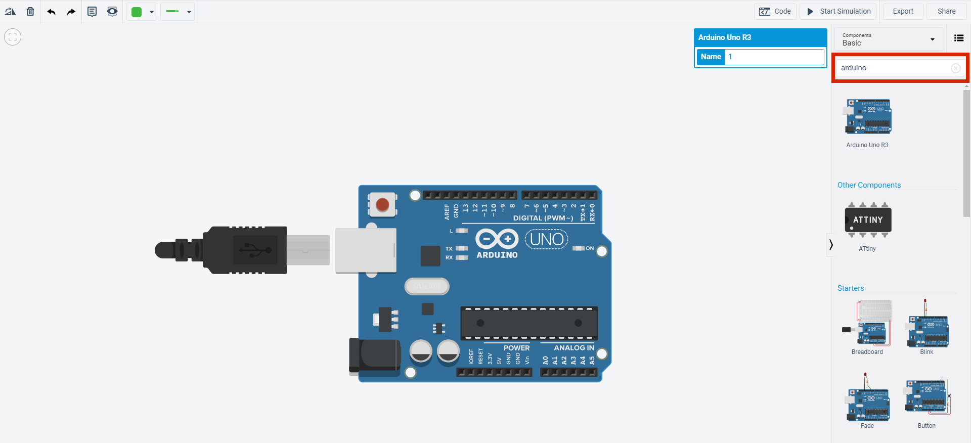
The Arduino is a prototyping platform, which means it allows you to build projects involving electronics and programming. You already have everything you need for the programming part. Now, we’re going to build an electric circuit.
4. Search for “board”. Drag the Breadboard Mini to the workplane.
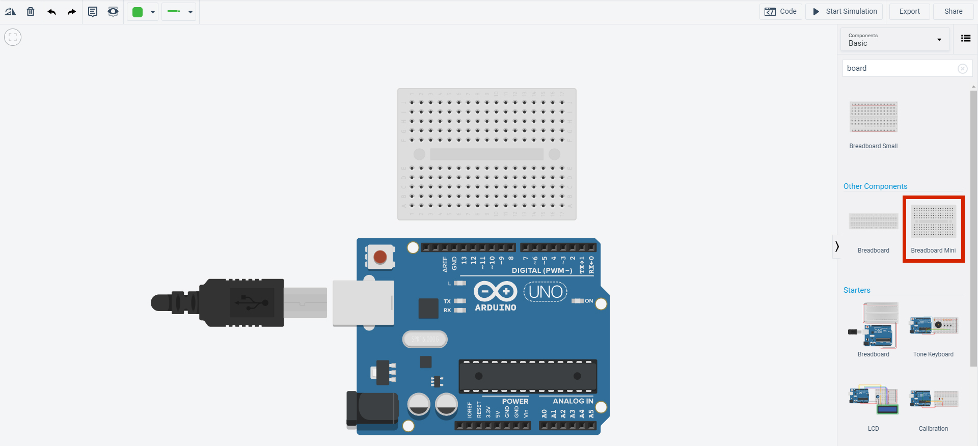
This is the board you’re going to build your circuit on. The breadboard has lots of little holes connected to each other via columns. These allow you to simplify circuits by avoiding the use of lots of wires.
5. Let’s build this circuit:
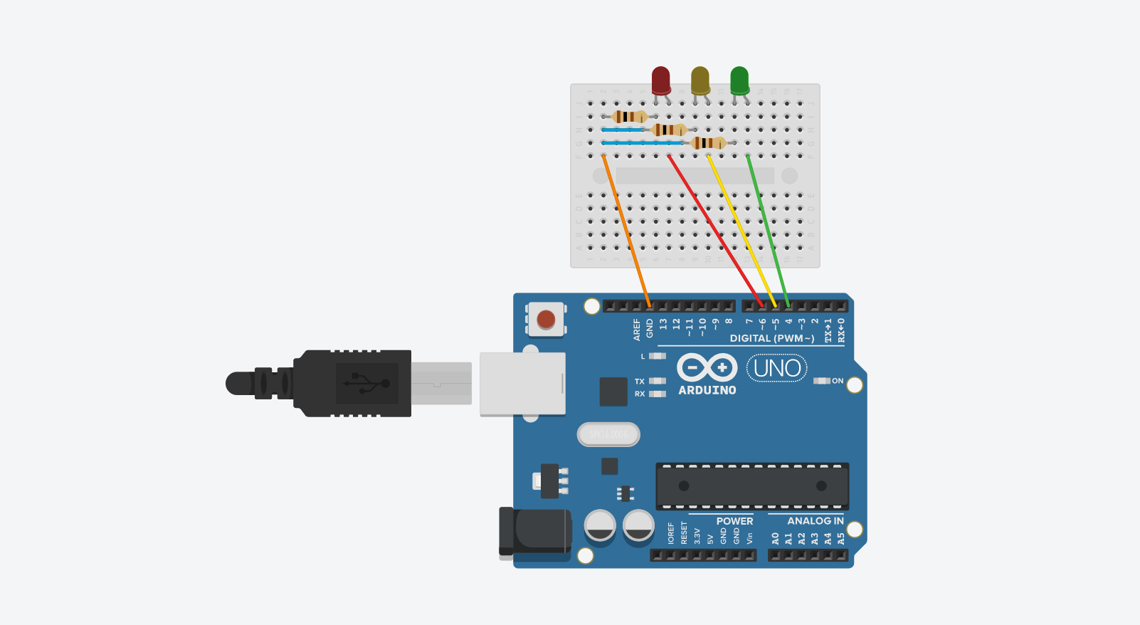
For this circuit, you’ll need 3 LEDs (1 red, 1 yellow and 1 green. Change the color of each LED after placing it in the Workspace) and 3 resistors. LEDs are components that give off light and can be in different colors. They have two legs; a shorter one, which is the negative and a longer one, which is the positive.
The longer leg should be connected to a digital pin (numbered pins on the Arduino). Don’t mix them up:
• The red wire connects the red LED to pin 6;
• The yellow wire connects the yellow LED to pin 5;
• The green wire connects the green LED to pin 4.
The circuit receives electricity from the Arduino. But, there’s too much electricity for what you want to do. We use resistors to get rid of this “excess” energy. Put the resistors as you see in the image, connecting them to the LEDs’ shorter legs and to the GND pin with the orange wire.
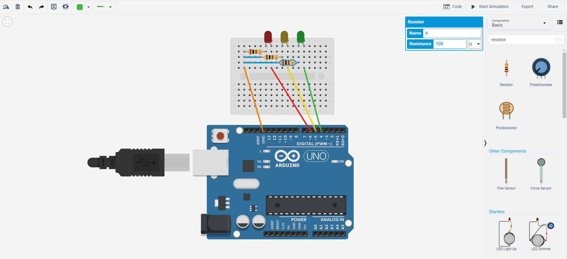
A unidade de medida da resistência elétrica é o ohm (Ω). Quando colocas a resistência na placa, irá aparecer uma caixa para alterares o valor da resistência. Para este circuito, altera as definições de todas as resistências para 100Ω, escrevendo “100” no valor da resistência e selecionando a unidade Ω.
6. Now that you’ve set up your circuit, you can give it instructions: using code to tell it what it has to do. Click on Code, then select Text from the box at the bottom. Click on Continue so that you can write this code:

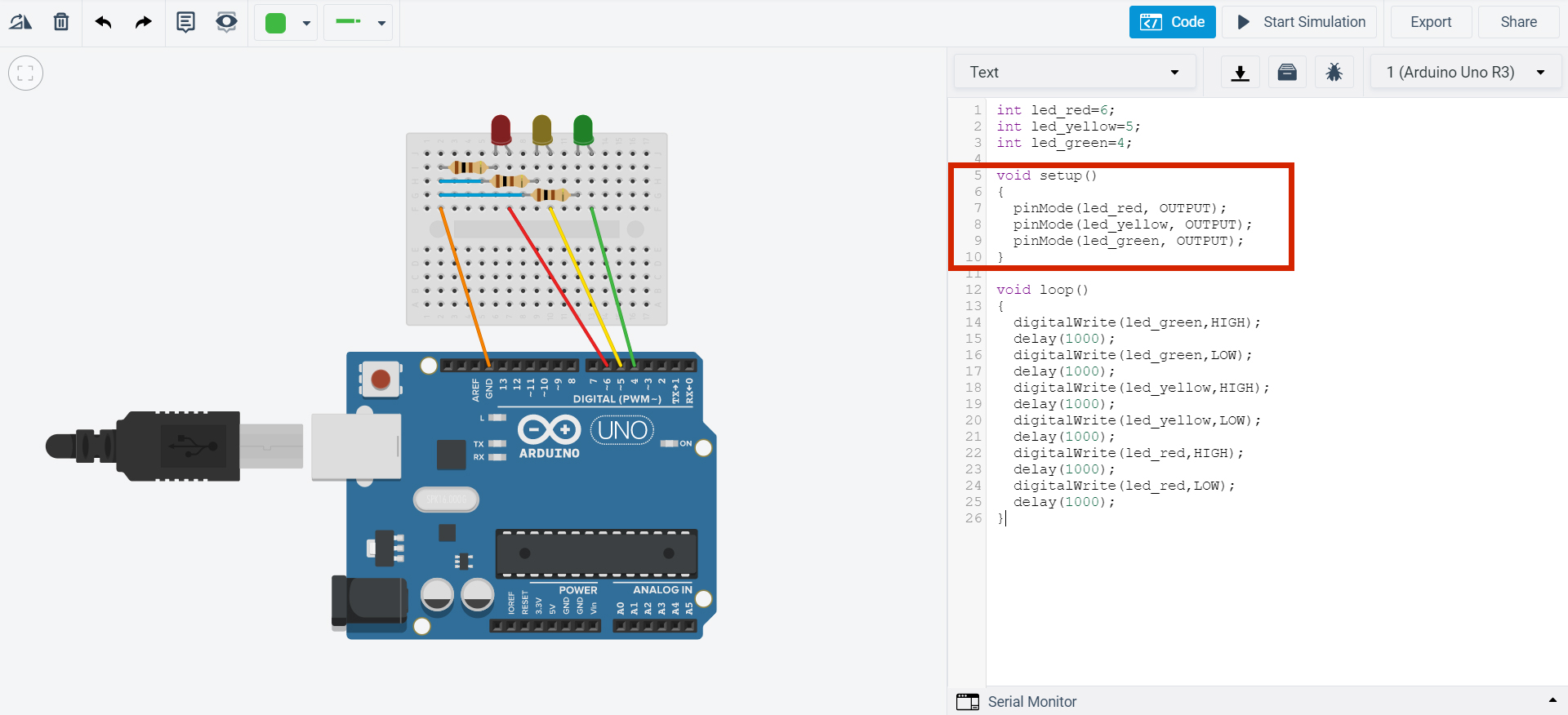
7. In the blue area, you can give a name to each one of the LEDs based on their color and identify the pins they’re connected to. For example, the red LED is called “led_red” and is connected to pin 6, so the code for this LED is int led_red = 6.
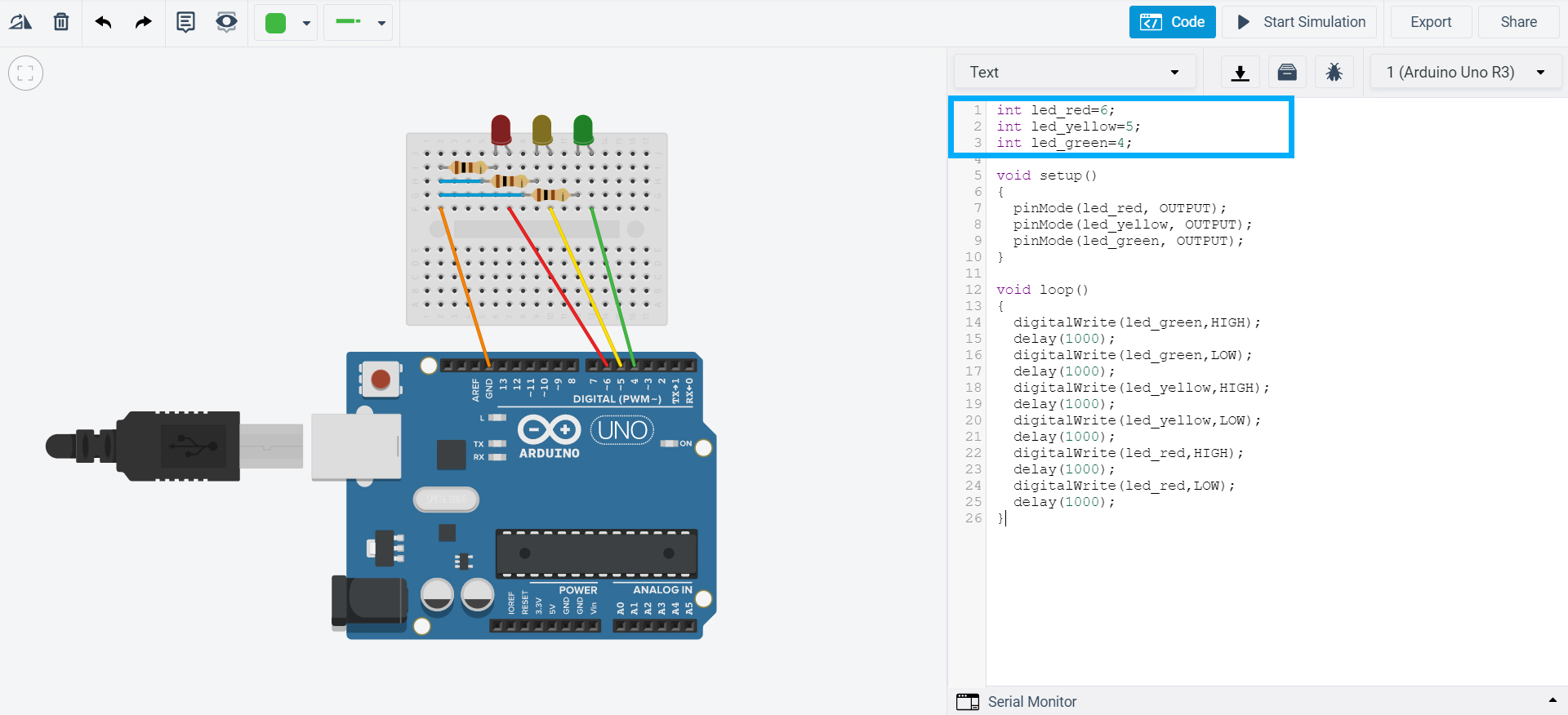
PinMode() is used in the red area. This tells the computer if a certain component is giving or receiving information. In our case, it shows that the LED was giving (INPUT) or receiving (OUTPUT) information from the Arduino. As it’s the Arduino that’s “telling” the LEDs to do something, they’re all receiving information so they’re all identified with the OUTPUT code. The previous code is written “inside” the void setup(). Everything written inside the void setup() is read by the Arduino once only.
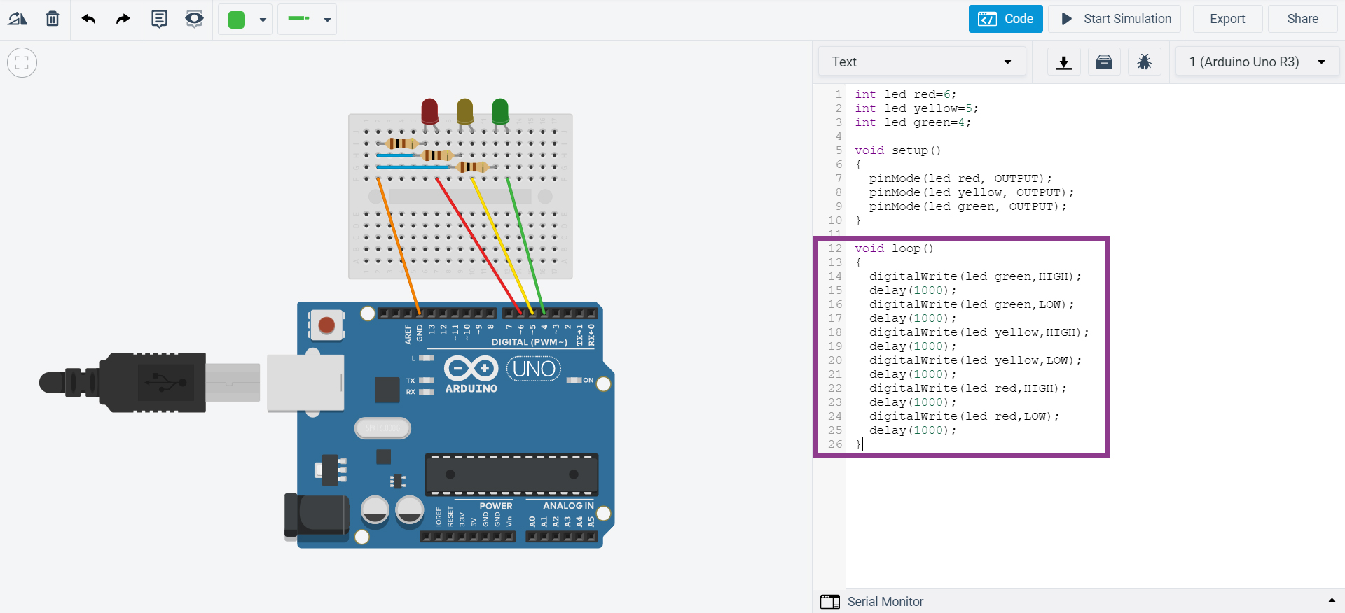
The purple area is for telling the LEDs what they have to do. For example:
• when you write digitalWrite(led_green, HIGH), you’re telling the green LED (led_green) to turn on (HIGH);
• next, the code asks it to wait 1 second, using delay(1000); The delay() is counted in milliseconds: 1000 ms = 1 s;
• then, write digitalWrite(led_green, LOW). This way, you’re telling the green LED (led_green) to turn off (LOW);
The code is written “inside” the void loop(). Everything written inside the void loop() is read by the Arduino infinite times (until you tell it to stop).
8. Click on Start Simulation and see what happens. You’ll see that the LEDs are flashing like traffic lights!
Explore Tinkercad and create new circuits with the Arduino.